
1. Sealing theory
The function of the seal is to prevent leakage. There are two reasons for leakage: one is the gap on the sealing surface; the other is the pressure difference on both sides of the seal. Elimination or reduction of either factor can prevent or reduce leakage. But for general equipment, eliminating gaps is the main way to prevent leakage.
1. Packing sealing mechanism
The packing is loaded into the packing cavity and compressed axially by the gland. When the shaft and the packing move relative to each other, due to the plasticity of the packing, it generates radial force and is in close contact with the shaft. At the same time, the lubricant impregnated in the filler is squeezed out, forming an oil film between the contact surfaces. Because the contact state is not very uniform, the contact part will appear "boundary lubrication", which is called the "bearing effect", while the uncontacted concave part forms a small oil groove with a thicker oil film. The regular maze plays the role of preventing leakage, which is called the "maze effect". This is the mechanism of the filler. Obviously, a good seal is to maintain the "bearing effect" and "labyrinth effect", that is, to maintain good lubrication and proper compression. If the lubrication is poor, or the pressure is too tight, the oil film will be interrupted, causing dry friction between the packing and the shaft, and finally causing the shaft to burn or cause serious wear.
For this reason, it is necessary to frequently adjust the packing compression degree so that the lubricant in the packing will be lost after a period of operation, while compensating for the packing relaxation caused by volume changes. Obviously, the packing is often squeezed in this way. The impregnant will be exhausted, so it is necessary to replace the filler regularly. In addition, in order to maintain the liquid film and take away the frictional heat, it is necessary to intentionally allow a small amount of leakage at the packing. Generally, see Table 1 for the allowable leakage of packing seals for rotating shafts.

2. Packing size calculation
Packing size can be calculated according to the following formula:
S=(D-d)/2=(1.4~2)d1/2
where D——the diameter of the inner wall of the stuffing box, in mm;
D——shaft diameter, in mm.
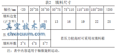
After the above formula is calculated, rounding is performed, and then a suitable packing is selected. Refer to Table 2.

3. Flexible graphite packing
Flexible graphite filler removes impurities in natural graphite, and expands between graphite layers through oxidation treatment to obtain the base material of flexible graphite—expanded graphite particles. The volume after expansion can reach 80-200 times the volume of the original graphite, and then processed into a square filler. In order to facilitate installation, the packing can be cut with a square cut (45° to the shaft), and the cuts between adjacent ones should be staggered. The shaft surface roughness Ra=6.3~3.2μm. For the seal of the pump shaft, it is better to be less than 1.6μm to avoid overheating and wear of the packing during the working process. The total length of the packing is 1.0 to 1.5 times the shaft diameter. The packing ring should be installed loosely and slidingly, so that it is comfortable to handle, not too tight. It is best to coat a layer of lubricant on the mating surface. Before starting, the gland should not be pressed too tightly. After starting, slowly adjust the gland bolt to "no leakage" or "slight leakage".
4. Reasonable filling and use of filler
1) Clean the inner cavity of the packing and check whether there are scratches and burrs on the surface.
2) Use a dial indicator to check the radial runout of the shaft at the sealing part, and the tolerance should be within the allowable range.
3) Filler or lubricant suitable for the medium should be coated in the filler cavity.
4) For packing in rolls, take a wooden stick with the same size as the shaft diameter when using it, wrap it on it, and then cut it with a knife. The cut can be flat, but it is best to have a 45° bevel.
5) The packing should be filled one by one, not several at a time. When the number of fillers is 4 to 8, the interfaces should be staggered by 90° during filling; the two fillers should be staggered by 180°; and 3 to 6 fillers should be staggered by 120° to prevent leakage through the incision.
6) After the last one is installed, the gland should be pressed tightly, but the pressure should not be too high. Rotate the main shaft at the same time, so that the compression force after assembly tends to be parabolic. Then loosen the gland slightly, and the filling is completed.
7) Carry out a running test to check whether the sealing requirements are met and verify the degree of heat generation. If it cannot be sealed, press the packing tightly; if the heat is too large, relax it.
8) Leakage should be checked frequently. If the leakage exceeds the allowable value, it should be tightened and adjusted in time.
9) Abrasion, bending, and eccentricity of the shaft are the main causes of leakage. The use of the bearing should be checked regularly, and the packing should be installed as close as possible to the bearing. The allowable radial runout of the shaft should preferably be below.
10) Fillers with different hardness and softness will have a good effect when used, but the hard filler should be deep when filling, and the soft filler should be near the gland.
11) The packing should be updated regularly. When disassembling, take care not to scratch the inner wall of the stuffing box and the surface of the shaft.
12) When the packing does not match the size of the packing cavity, it is strictly forbidden to knock the packing flat with a hammer.
2. Practical application
1. Fact analysis
In production practice, the butterfly valve shaft end often leaks. No matter how different the form and structure of the filler are, it can be attributed to the following reasons:
1) The surface roughness of the shaft and the inner cavity of the stuffing box does not meet the pattern requirements.
2) The packing itself allows a certain amount of leakage (refer to the above sealing theory).
3) The lubricant applied to the inner cavity of the stuffing box and the surface of the shaft is uneven.
4) Knocking during filling deforms the filling.
5) There is a problem with the filling sequence, which does not meet the requirements of soft packing near the gland and hard packing in the deep part. However, if the filling method provided by Aizhi manufacturer is used, the outermost ring packing should be anti-wear effect, and then the soft packing should be appropriately increased by 1 to 2 turns.
2. Solution
Based on the reasons analyzed above, several solutions are proposed below, and the best solution is verified through experimental means.
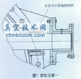
(1) Scheme 1 still adopts the original structure, but needs to increase the surface roughness of the related parts. It is required to increase the surface roughness of the shaft and the stuffing box to more than 3.2μm, and on the basis of theoretical calculations, add fillers appropriately The number of turns. When filling the packing, strictly follow the correct filling method, as shown in Figure 1.

(2) Scheme 2 If scheme 1 cannot achieve sealing, or it is difficult to achieve sealing, a rubber ring of appropriate size can be added to the outermost layer of the packing to test the sealing effect, as shown in Figure 2.

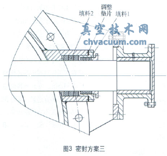
(3) Scheme 3 adopts double-layer seal, as shown in Figure 3, and uses the device shown in the figure to test. In the figure, packing 1 can be ordinary packing and can be replaced at any time, and packing 2 is high-quality packing. And through calculation, choose a reasonable adjustment gasket to press the packing 2 well.

3. Conclusion
The shaft end seal of butterfly valve not only depends on the choice of sealing material, but also depends on its processing and assembly adjustment accuracy.